Introduction
Almost all modern systems require cooling. Usually this is managed through air movement controlled by a fan. Other solutions exist for cooling but the fan is the most common). In some implementations these fans are always powered, but many have some controls, and some have monitoring of their current state as well.
Any system may have a number of these fans and they may be located in different positions within the computer system, or even outside it. The FanController module provides a means by which drivers may expose controls and information about the attached fans.
The FanController module allows the following operations to be performed on a fan:
- Listing the known fans.
- Reading the fan speed.
- Setting the fan speed.
- Changing driver control type, from manual to automatic.
The FanController module does not perform management or regulation of the fans within the system.
Terminology
Fan - A device which provides thermal regulation of devices.
Fan Driver - A module which provides information and/or control for a fan.
Location - A physical position in which a fan may be placed, relative to the computer system.
Technical details
Structure
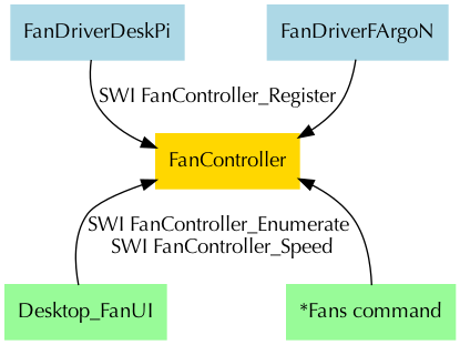
The FanController module provides an interface which users can call to obtain information about the fans attached to the computer system. It does so through registered drivers which can control a single fan. Applications and tools call the FanController to request information about the fans. The FanController dispatches the requests, if necessary, to the drivers which handle the fans.
Fans
Although Fans within the context of the FanController are generally considered to be devices that move air to perform cooling, there are other mechanisms for cooling. These can still be managed through the FanController system, although it is recommended that they express their function in terms of the duty-cycle percentage, rather than RPM speed.
Fans can be operate in one of three modes of control:
- Manual control. In this mode, the fan is given speeds by the user, and it runs at that speed until a new speed is given.
- Automatic control. In this mode, the fan driver is controlling the speed, and attempts by the user to change the fan speed will be ineffective. This mode will be offered by fan drivers which can either control the speed themselves, or which interface with hardware which offers an automatic management mode.
- Managed control. In this mode, the fan driver is being managed by another module within the system. This control mode is informational, as the operations to control the speed will be effective, but the managing module will override the speed controls as it manages the fan. Fan drivers are never informed that they are running in 'managed' mode - to them it appears that they are under manual control. User interface components should not allow manual changes to fans which are under managed control.
They can be controlled to operate at specific speeds, usually reported in RPM. Or they can be controlled as fractions of their full speed, reported as a percentage. The fan may be unable to report a speed if it has no explicit controls - it may only be able to be turned on and off. Some fans may be able to report that they have failed, either because they are detected as broken, or monitoring reports that they are not performing correctly.
Most fans do not have completely variable controls, and do not allow any set of speeds to be selected. The Fan driver may declare the speeds which the fan can achieve or the accuracy at which it select them. For example, a given fan might only be able to run at 2200, 3000, 3400 and 3900 RPM, and so would report those as the only speeds it provides. Or it might only be able to control the percentage at 10% intervals, so would report an accuracy of 10%.
Speed
The following fan speeds values and ranges are used within the FanController interfaces:
| Value | Meaning |
|---|---|
| <= -3 | Reserved for future error codes |
| -2 | Error: Fan has failed |
| -1 | Error: Fan is disconnected |
| 0 | Fan is disabled |
| 1-100 | Fan is duty-cycle (or equivalent) controlled, to a percentage value. 0 and 100 may be used for binary controlled fans |
| 101 | Fan operating under automatic control and its speed is not determined |
| >= 200 | Fan speed in RPM |
Control mode
Fans may be placed into different control modes. Not all fans will support all modes, and this will be indicated by the fan capability flags. The following control modes are used within the FanController interfaces:
| Value | Meaning |
|---|---|
| -1 | Fan system error |
| 0 | Manual speed control (user is controlling the speed) |
| 1 | Managed speed control (system component is controlling the speed) |
| 8 | Automatic speed control (favour performance) |
| 9 | Automatic speed control (favour quietness) |
| 10-15 | Automatic speed control (reserved for future expansion) |
Capability flags
Fan drivers may have different capabilities, and may be able to support different modes of operation. These can be declared through the capabilities flags. This is a 32bit value containing bit values which describe what the fan can do.
| Bit(s) | Meaning | |||||||||||||
|---|---|---|---|---|---|---|---|---|---|---|---|---|---|---|
| 0 | Set: | Fan supports manual configuration | ||||||||||||
| Clear: | Fan does not support manual configuration | |||||||||||||
| 1 | Set: | Fan supports automatic configuration | ||||||||||||
| Clear: | Fan does not support automatic configuration | |||||||||||||
| 2 | Set: | Fan supports changing location | ||||||||||||
| Clear: | Fan does not support changing location | |||||||||||||
| 3 | Set: | Fan may report failure errors | ||||||||||||
| Clear: | Fan cannot report failure errors | |||||||||||||
| 4-27 | Reserved, must be 0 | |||||||||||||
| 28-31 | Cooling device type:
| |||||||||||||
The FanController module will use these capabilities to restrict the calls that can be made and avoid calls to the FanDriver.
Location identifier
Fans may be located in different positions relative to the system which is reporting their state. Each fan must supply a location identifier which describes where the fan is located. This is an enumerated set which should allow user interfaces give a visual representation, or description, of the fan locations. Fan locations are broken down into three major parts, held in a word:
| Bit(s) | Meaning | |
|---|---|---|
| 0-7 | Location identifier, dependant on the device type | |
| 8-15 | Sequence number, dependant on the device type | |
| 16-23 | Device type | |
| 24-31 | Reserved, must be 0 | |
Device type - this indicates the area or entity that the fan is associated with. This allows the user to identify what type of device the fan is trying to cool. The following device types are defined:
Value Meaning 0 CPU device 1 GPU device 2 Memory device 3 I/O card 4-15 Reserved for discrete internal components 16 PSU fan 17 Backplane fan 18 Radiator fan (fans attached to radiators on passive or active cooling) 19 Chassis fan 20-31 Reserved for macro internal components 32 External fan 33-239 Reserved for other devices 240-254 Reserved for users 255 Generic fan, unknown properties - Sequence number - this gives more information about which device or location is being described. The meaning differs depending on the device type. For internal devices this sequence number describes the instance of the device which is being cooled. For example, where multiple CPUs exist, each fan will be associated with the CPUs by the sequence number.
- Location - The location in relation to the device. The meaning of this field is dependant on the device type.
Each of these device types has an assignment for the location and sequence number within the location identifier. This allows more specific locations to be supplied to the user.
CPU device
Fan locations
| Value | Meaning |
|---|---|
| 0 | On chip |
| other | Reserved for future expansion |
Sequence numbers
The sequence number describes the CPU number to which the fan is attached. The value 255 should be used for unknown CPU numbers.
GPU device
Fan locations
| Value | Meaning |
|---|---|
| 0 | On chip |
| other | Reserved for future expansion |
Sequence numbers
The sequence number describes the GPU number to which the fan is attached. The value 255 should be used for unknown GPU numbers.
Memory device
Fan locations
| Value | Meaning |
|---|---|
| 0 | On module (where a fan cools a single module) |
| 1 | On CPU bank (where a fan cools a bank of memory modules associated with a CPU) |
| 2 | On channel (where a fan cools a single channel for a bank of modules) |
| 3 | On riser (where a fan cools a collection of memory modules on a riser card) |
| other | Reserved for future expansion |
Sequence numbers
The sequence number describes the component to which the fan is attached. The value 255 should be used for unknown component numbers.
I/O card
Fan locations
| Value | Meaning |
|---|---|
| 0 | On card |
| other | Reserved for future expansion |
Sequence numbers
The sequence number describes the card to which the fan is attached. The value 255 should be used for unknown card numbers. The meaning of this card number is implementation defined.
PSU fans
Fan locations
| Value | Meaning | ||||||||||||||||||||||||||||||||||||||||||
|---|---|---|---|---|---|---|---|---|---|---|---|---|---|---|---|---|---|---|---|---|---|---|---|---|---|---|---|---|---|---|---|---|---|---|---|---|---|---|---|---|---|---|---|
| 0-63 | Position described within the logical space of the device, as described by facing the front of the device:
| ||||||||||||||||||||||||||||||||||||||||||
| 64-254 | Reserved for future expansion | ||||||||||||||||||||||||||||||||||||||||||
| 255 | Unspecified location | ||||||||||||||||||||||||||||||||||||||||||
Sequence numbers
The sequence number distinguishes multiple devices in the specified location.
Backplane fans
Fan locations
Backplane fans use the same fan locations as described in PSU fans, above.
Sequence numbers
The sequence number distinguishes multiple devices in the specified location.
Radiator fans
Radiator fans are fans which are attached to cool the radiators used by active or passive cooling systems such as heat pipes or liquid cooling heat exchanges.
Fan locations
Radiator fans use the same fan locations as described in PSU fans, above.
Sequence numbers
The sequence number distinguishes multiple devices in the specified location.
Chassis fans
Fan locations
Backplane fans use the same fan locations as described in PSU fans, above.
Sequence numbers
The sequence number distinguishes multiple devices in the specified location.
External fans
Fan locations
| Value | Meaning |
|---|---|
| 0 | UPS |
| 1 | External drive array |
| 2 | External device |
| 64 | Desk fan |
| 65 | Aircon |
| 255 | Unspecified location |
Sequence numbers
The sequence number distinguishes multiple devices in the specified location.
Generic fans
Fan locations
| Value | Meaning |
|---|---|
| 0 | Unknown location |
Sequence numbers
The sequence number may be used to distinguish devices.
Fan registration
Fans are registered with FanController through SWI FanController_Register when they are detected. If they are removed, or the driver is terminated, the fan is deregistered with SWI FanController_Deregister. On registration the fan will be assigned an identifier which is unique to this execution of the FanController. The fan identifiers will be recycled if the FanController is restarted.
Change notifications
The FanController will issue notifications as its state changes. This allows other modules and applications to recognise and handle these transitions. For modules, service calls are issued for the state transitions. For applications, a pollword may be updated to indicate that the state of the fans has changed. Strictly, modules could also use the pollword system, although it would be less efficient than simply using the pollwords.
The SWI FanController_TaskPollWord interface allows applications to recognise events by one of three bits being set - a bit which indicates that the controller has died, a bit which indicates that the registrations have changed, and a bit which indicates that fan error state has changed. These notifications are coarse (they do not indicate which fan identifier has been changed) because pollwords are limited to only 32bits, and it is therefore not possible to communicate more information. Applications should act appropriately to locate whether the devices they are interested in have changed.
After the FanController module has started, it will issue Service_FanController_Started on a callback. This allows drivers to register themselves with the FanController. Services are delivered to modules in order of the module registration, and the state of the system may change between initialisations, so fan drivers (and other users of FanController) must not rely on being given the same fan identifier between initialisations.
When the FanController module is killed, it will issue Service_FanController_Dying. At that point, all drivers have been automatically deregistered. Fan drivers should take note that they are no longer registered, and users of the fan system should forget all fan identifiers. Application pollwords will be updated to indicate that the module has died, and applications seeing this bit indicated should treat all fan identifiers as invalid and begin any fan identification process as necessary.
When a new fan is registered or an existing fan is deregistered, the FanController will issue Service_FanController_FanChanged. This allows modules to recognise the coming and going of fan drivers and to update their state appropriately. Application pollwords will be updated to indicate that the registrations have changed. Applications should enumerate the fans to identify whether the fan(s) that they are monitoring have been affected. In many cases, this may just be a new fan driver being loaded, or an existing fan driver being re-initialised. In the former case, the enumeration will show up the new fan. In the latter case, fans being monitored may still be present in the enumeration, but will have changed their fan identifier.
When a fan driver identifies an error state (or that an error state has been resolved) it should issue Service_FanController_FanChangedState. This notifies any modules that the fan is (or is no longer) reporting an error. This state change is reported by the fan driver directly, as it will recognise the error state and can report the information to the FanController and other modules through the service. The FanController will record this error state notification, and will update the application pollwords to report the error condition. Applications should note that the error state may have already been resolved by the time they receive the notification through the pollword.
Fan speed changes are not notified through the service calls. Speed changes could happen many times per second, and can affect every single device. As such, notifications would themselves become a significant part of the system's processing. Additionally, the fan speed may be automatically managed by a fan controller, and the speed be only a value that the driver can read. Such cases make it impossible to accurately report that the speed has changed. Applications and modules wishing to track fans should provide a configurable cadence for polling for the fan speed to allow an appropriate trade off between system utilisation and responsiveness. In many cases, a polling period measured in seconds will have a negligable effect on performance, and interface updates at that speed would be acceptable to most users.
Service calls
| R0 | = | API version * 100 |
| R1 | = | Service number (&10080) |
| R0 | preserved | |
| R1 | preserved | |
This service is issued by FanController on a callback once the module has initialised. On receipt of this service, fan drivers may register the fans that they control with the module. Drivers may call any of the FanController SWIs.
| R1 | = | Service number (&10081) |
| R1 | preserved | |
This service is issued by FanController when it is killed. No further SWI calls should be made to the module. It is should be assumed that all registered fans are no longer registered.
| R0 | = | Fan identifier |
| R1 | = | Service number (&10082) |
| R2 | = | 1 if a fan has been registered, 0 if a fan has been deregistered |
| R0 | preserved | |
| R1 | preserved | |
| R2 | preserved | |
This service call is issued by FanController when the list of fans has been changed, either by registration or deregistration.
| R0 | = | Fan identifier |
| R1 | = | Service number (&10082) |
| R2 | = | Fan state, as a speed - either a negative value or a speed |
| R0 | preserved | |
| R1 | preserved | |
| R2 | preserved | |
This service call may be issued by a fan driver if it detects a transition into or out of an error state. The new state, given in R2, indicates either an error condition, or a regular fan speed (>= 0) to indicate that a fan has begun working. This service call should not be issued for changes in speed when running normally.
SWI calls
| R0 | = | Version number of the API * 100 (1.01 for this version) |
This SWI is used to read the API version for the FanController module. Updated minor versions may introduce new features to the API. Major versions will be incompatible.
| R0 | = | 0 for first call, or value from previous call to continue enumeration |
| R0 | = | Fan identifier of this fan, or -1 if there are no more entries to enumerate |
| R1 | = | Location identifier for this fan |
| R2 | = | Capability flags for this fan |
| R3 | = | Pointer to the provider name for this fan |
| R4 | = | Speed accuracy, in RPM, or values 1-100 for duty-cycle control, or 0 for unknown accuracy |
| R5 | = | Maximum supported speed in RPM, or 100 if fan uses duty-cycle control or can only be turned on and off, or -1 if unknown |
| R6 | = | Pointer to a table of words describing the supported speeds, terminated by a -1 word, or 0 if arbitrary speeds (constrained by the accuracy) may be used. |
This SWI is used to enumerate the fans which are known to the FanController module. It should be called initially with R0 = 0 and each subsequent call should supply the fan identifier returned from the previous call. The enumeration terminates with the return of a -1 in R0, indicating that there is no more data (and that the other registers are not populated).
Enumeration is not guaranteed to be in strictly ascending order of fan identifiers. If an ordered list is desired, the caller should sort the returned values.
| R0 | = | Fan identifier to get information on |
| R0 | = | Fan identifier |
| R1 | = | Location identifier for this fan |
| R2 | = | Capability flags for this fan |
| R3 | = | Pointer to the provider name for this fan |
| R4 | = | Speed accuracy, in RPM, or values 1-100 for duty-cycle control, or 0 for unknown accuracy |
| R5 | = | Maximum supported speed in RPM, or 100 if fan uses duty-cycle control or can only be turned on and off, or -1 if unknown |
| R6 | = | Pointer to a table of words describing the supported speeds, terminated by a -1 word, or 0 if arbitrary speeds (constrained by the accuracy) may be used. |
This SWI is used to return information about a specific fan. The returned parameters are the same as those returned by the FanController_Enumerate call.
| R0 | = | Fan identifier to read or set |
| R1 | = | Speed to set the fan to, or -1 to read the current speed |
| R0 | preserved | |
| R1 | = | Current speed when reading the speed, or the selected speed if setting the speed |
This SWI is used to read or set the speed of the fan. It is an error to attempt to select one of the negative values for the fan speed (which indicate errors). Selecting a fan speed which is not one of the valid speeds for the fan may select the closest speed which can be achieved.
| R0 | = | Fan identifier to configure | ||||||
| R1 | = | Reason code for configuring the fan:
| ||||||
| R2 | = | Parameter to configure |
| R0 | preserved | |
| R1 | preserved | |
| R2 | = | Result parameter |
This SWI is used to configure the fan beyond the basic fan speed. Consult the individual reason codes for more detail on the operation.
| R0 | = | Fan identifier to configure |
| R1 | = | Reason code (0) |
| R2 | = | Control mode or -1 to read the control mode |
| R0 | preserved | |
| R1 | preserved | |
| R2 | = | Current control mode |
This SWI is used to configure how the fan speed is controlled. When under manual control, the fan remains at the speed set. When under automatic control, the fan reacts to the system to control its speed. The manner in which it detects its needs is implementation defined.
| R0 | = | Fan identifier to configure |
| R1 | = | Reason code (1) |
| R2 | = | New location identifier for this fan |
| R0 | preserved | |
| R1 | preserved | |
| R2 | = | New location identifier |
This SWI is used to change the location reported by the fan. The location identifier is purely informational, but it may be useful to allow the user to change the location, particularly in fans whose location is configurable, or for which the interface to which they are connected has no means of determining a location. For example, a serial controlled fan might be fitted in many locations in a chassis which would not be identifiable to the driver.
| R0 | = | Pointer to word-aligned pollword |
| R1 | = | Bit number (0-31) to set when FanController dies, or -1 to set no bit |
| R2 | = | Bit number (0-31) to set when a driver is registered or deregistered, or -1 to set no bit |
| R3 | = | Bit number (0-31) to set when a driver changes its error state, or -1 to set no bit |
| R0 - R3 | preserved | |
This SWI is used to register or deregister a pollword with the FanController module. If all the registration bits are supplied as -1, the pollword will be deregistered. The pollword address supplied in R0 must be in globally addressable memory (such as the relocatable module area), and must be writeable in SVC mode.
When the FanController reaches one of the three events (FanController death, driver registration/deregistration, or driver error state change) it will update the pollword by setting the bit requested. Applications may use the pollword in their SWI Wimp_Poll calls. On servicing the pollword event, it is the responsibility of the application to clear the pollword bits.
This SWI was added in API version 1.01.
| R0 | = | Pointer to driver code entry point |
| R1 | = | Workspace value to pass in R12 to the entry point |
| R2 | = | Location identifier for this fan |
| R3 | = | Capability flags for this fan |
| R4 | = | Pointer to the provider name for this fan |
| R5 | = | Speed accuracy, in RPM, or values 1-100 for duty-cycle control, or 0 for unknown accuracy |
| R6 | = | Maximum supported speed in RPM, or 100 if fan uses duty-cycle control or can only be turned on and off, or -1 if unknown |
| R7 | = | Pointer to a table of words describing the supported speeds, terminated by a -1 word, or 0 if arbitrary speeds (constrained by the accuracy) may be used. |
| R0 | = | Fan identifier assigned to this fan |
This SWI is used to register a new fan with the FanController module. The fan will be announced using Service_FanController_FanChanged. The fan will appear in the list of enumerated fans, and may be controlled once this call has returned.
| R0 | = | Fan identifier to deregister |
| R0 | preserved | |
This SWI is used to deregister a new fan from the FanController module. The fan's removal will be announced using Service_FanController_FanChanged.
Entry points
| R0 | = | Reason code:
| ||||||||||||
| R1 | = | Fan identifier to operate on | ||||||||||||
| R2 | = | Location identifier of the fan | ||||||||||||
| R3 - R9 | = | Dependant on reason code |
| R0 | = | Preserved if recognised, or -1 if reason code is not recognised |
| R1 - R9 | = | Dependant on reason code |
The FanDriver entry point is called by the FanController module to perform operations on the Fan. Where possible, the FanController will attempt to report on invalid values supplied to its SWIs before calling the FanDriver module.
| R0 | = | Reason code (0) |
| R1 | = | Fan identifier to operate on |
| R2 | = | Location identifier of the fan |
| R0 | preserved | |
| R3 | = | Fan speed |
This FanDriver entry point is called to read the current fan speed. The fan driver should return the speed of the fan, or one of the error codes.
| R0 | = | Reason code (1) |
| R1 | = | Fan identifier to operate on |
| R2 | = | Location identifier of the fan |
| R3 | = | Fan speed |
| R0 | preserved | |
| R3 | = | Fan speed |
This FanDriver entry point is called to set the current fan speed. The fan driver should return the speed of the fan that was actually selected, or one of the error codes. The speed will have been filtered by the FanController module to remove invalid values.
This entry point will not be called if the fan does not support manual speed setting.
| R0 | = | Reason code (2) |
| R1 | = | Fan identifier to operate on |
| R2 | = | Location identifier of the fan |
| R3 | = | Control mode |
This FanDriver entry point is called to read the current control mode for the fan. If the control mode cannot be changed, this entry point will not be called.
| R0 | = | Reason code (3) |
| R1 | = | Fan identifier to operate on |
| R2 | = | Location identifier of the fan |
| R3 | = | Control mode |
| R3 | = | Control mode |
This FanDriver entry point is called to set the control mode for the fan. If the control mode cannot be changed, this entry point will not be called.
| R0 | = | Reason code (4) |
| R1 | = | Fan identifier to operate on |
| R2 | = | Location identifier of the fan |
| R3 | = | New location identifier |
| R3 | = | Flag to indicate whether the change was allowed:
|
This FanDriver entry point is called to request that the fan's location be changed. The driver can decide whether the new location is reasonable or not and respond appropriately. For example, a Fan driver for a CPU fan might reject changes to a device which is not a CPU, or a driver for a chassis fan which may be placed at the front or rear may only allow those two locations.
Error messages
This error is returned when a fan identifier has been supplied which is not known.
This error is returned when an invalid reason code is supplied to FanController_Configure.
This error is returned when an invalid control mode is supplied for a fan to FanController_Configure.
This error is returned when the registration of a fan failed. This might be because there is insufficient memory to hold the registration, or because a limit has been reached on the fans.
An error occured during module initialisation which could not be recovered from.
This error is returned when FanController_SetSpeed cannot select the speed requested. This may happen if the speed requested was not valid, or is outside the range supported by the fan.
This error is returned when FanController_Configure 1 cannot change the location of the fan. This might be returned if the driver knows that the fan only exists in one location, and thus it cannot be repositioned.
*Commands
The *FansInfo command is used to display a list of the fans that are registered with FanController and their current state.
<fan-id> | - | Fan identifier number. |
<speed> | - | Fan speed, as a percentage 1-100, as an RPM over 200, or 0 to turn off. |
The *FanSpeed command can be used to display the speed of a specified fan, or to set its speed.
Examples
List the fans registered with FanContrller
REM List the fans we know about
fan_id% = 0
REPEAT
    SYS "FanController_Enumerate", fan_id%,,,"" TO fan_id%, location_id%, capabilities%, provider$, accuracy%, max%, speeds%
    IF fan_id% <> -1 THEN
        PRINT"FanID:        ";fan_id%
        PRINT"Location:     &";~location_id%
        PRINT"Capabilities: &";~capabilities%
        PRINT"Provider:     ";provider$
        PRINT"Accuracy:     ";accuracy%
        PRINT"Max speed:    ";max%
        IF speeds% THEN
            PRINT"Supported speeds:"
            ofs% = 0
            WHILE speeds%!ofs% <> -1
                PRINT"              ";speeds%!ofs%
                ofs% += 4
            ENDWHILE
        ENDIF
        PRINT
    ENDIF
UNTIL fan_id% = -1